Introduction: The Energy Challenge in Compressed Air Systems
Compressed air is often called the "fourth utility" of industry, accounting for 10-30% of total electricity consumption in manufacturing facilities. Industry surveys consistently show that over 90% of the electrical energy fed into an air compressor is lost as heat, friction, and throttling waste—only a small fraction is delivered as usable compressed air output.
The root cause of this waste lies in traditional compressor control: fixed-speed machines load and unload continuously to match fluctuating air demand. Every unload cycle vents compressed air to atmosphere (wasting 100% of the energy used to compress it), while every load cycle draws 7-8 times the motor's rated current at startup, stressing both the machine and the grid.
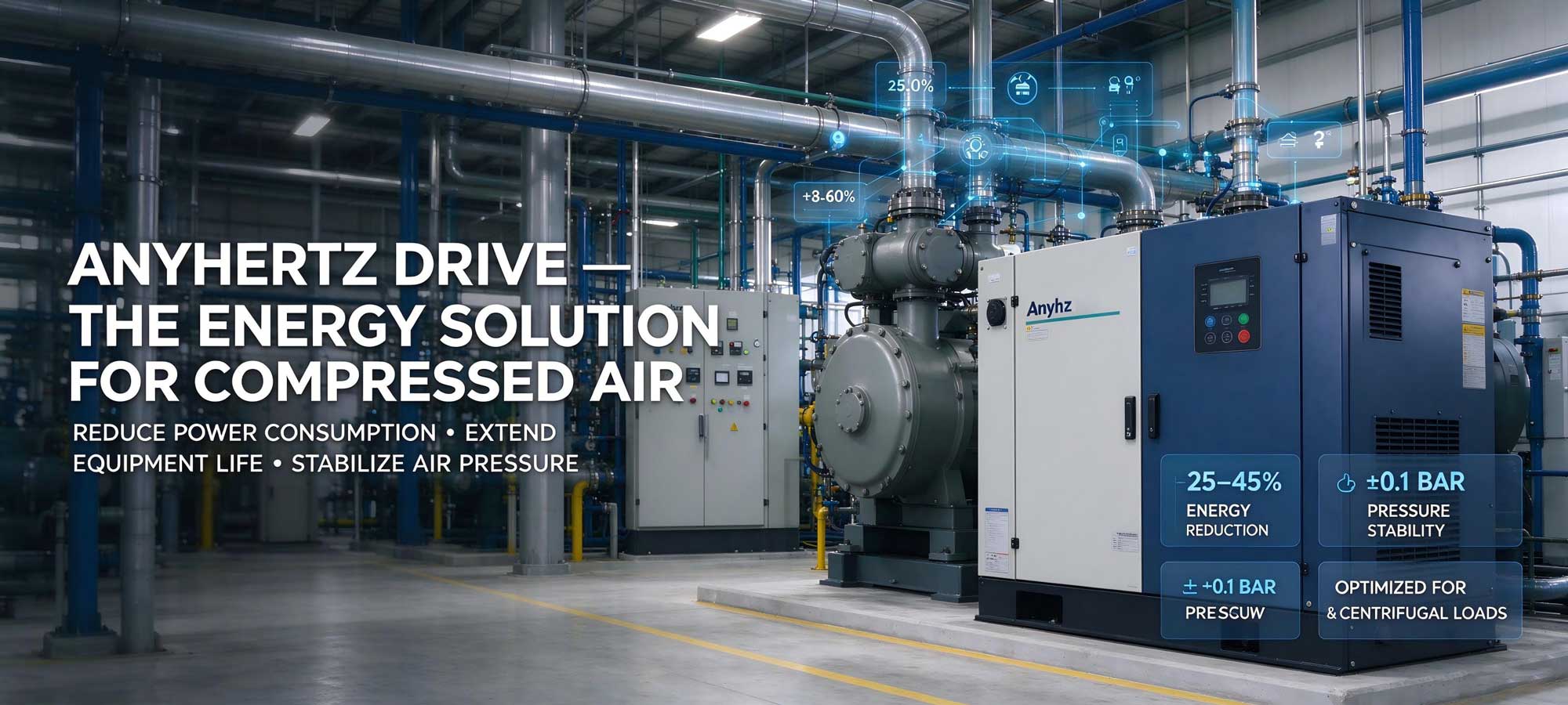
Variable Frequency Drive (VFD) technology eliminates this waste by allowing the compressor motor to run exactly at the speed required by real-time air demand. With nearly 20 years of R&D experience and 156+ patents, Anyhertz Drive (Shenzhen) Co., Ltd. provides specialized frequency converter solutions that help compressed air users achieve 25-45% energy reduction while improving air pressure stability and equipment reliability.
Section 1: Why Frequency Converters Are Essential for Air Compressor Systems
1.1 The Energy Waste Problem in Fixed-Speed Compressors
Traditional fixed-speed screw compressors rely on mechanical/hydraulic control methods:
-
Load/unload cycling: The motor runs at full speed continuously; excess air is vented through the intake valve during "unload" (energy waste of 25-40% of running time in typical plants)
-
Frequent starts: Direct-on-line starting causes 7-8x inrush current, motor winding stress, and grid voltage dips (most plants limit motors to 4-6 starts/hour, forcing minimum run times that waste even more energy)
-
Constant pressure overkill: System pressure must be set high enough to cover peak demand moments, meaning the compressor produces 0.5-1.0 bar more pressure than needed 80% of the time—and every extra bar costs 6-8% more energy
1.2 The Affinity Laws Advantage
Air compressor power consumption follows the square-cube relationship with speed: power decreases with the cube of speed reduction for centrifugal/blower-type loads, and decreases proportionally for screw compressors where air output scales with rotor speed. Reducing speed from 100% to 80% cuts energy consumption by approximately 30%, while maintaining exactly the pressure the plant actually needs.
1.3 Core Benefits of AnyHz Frequency Converter Solutions
| Benefit |
Technical Mechanism |
Business Impact |
|
Energy Savings
|
Speed matched to real-time air demand via PID closed-loop
|
25-45% reduction in electricity costs
|
|
Zero Unload Waste
|
Continuous modulation replaces load/unload cycling
|
Eliminates 100% vented-air waste
|
|
Soft Starting
|
Controlled acceleration 0-120s adjustable
|
Eliminates inrush current, extends motor and airend bearing life 3-5x
|
|
Stable Pressure
|
PID control holds pressure within ±0.1 bar
|
Improves product quality, reduces leak losses
|
|
Reduced Leakage
|
Lower average system pressure
|
Air leaks consume proportionally less air (saving an additional 3-5%)
|
|
No Start Limits
|
Unlimited starts/stops with VFD
|
Perfect for intermittent demand patterns
|
Section 2: AnyHz Frequency Converter Product Portfolio for Compressed Air
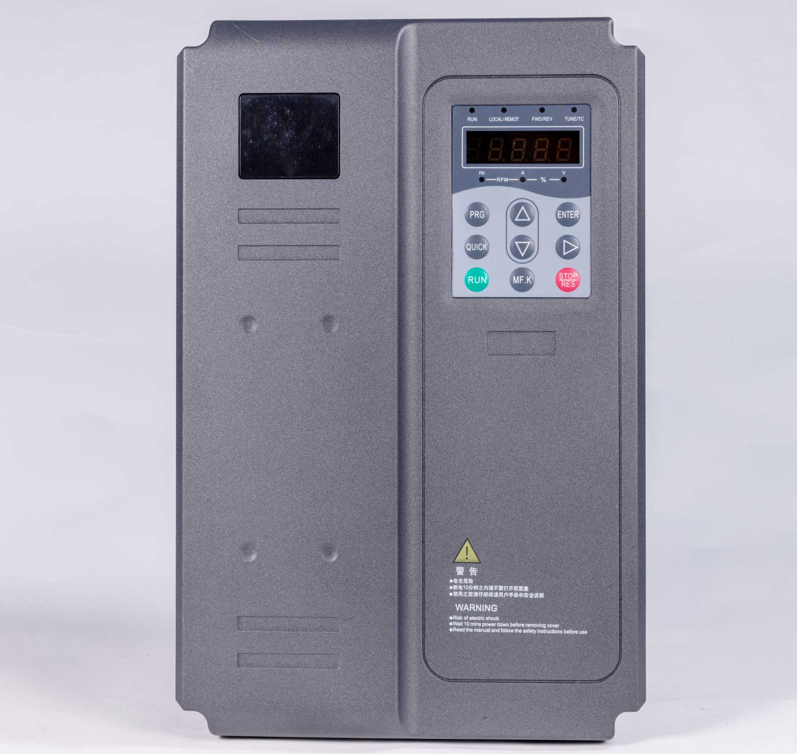
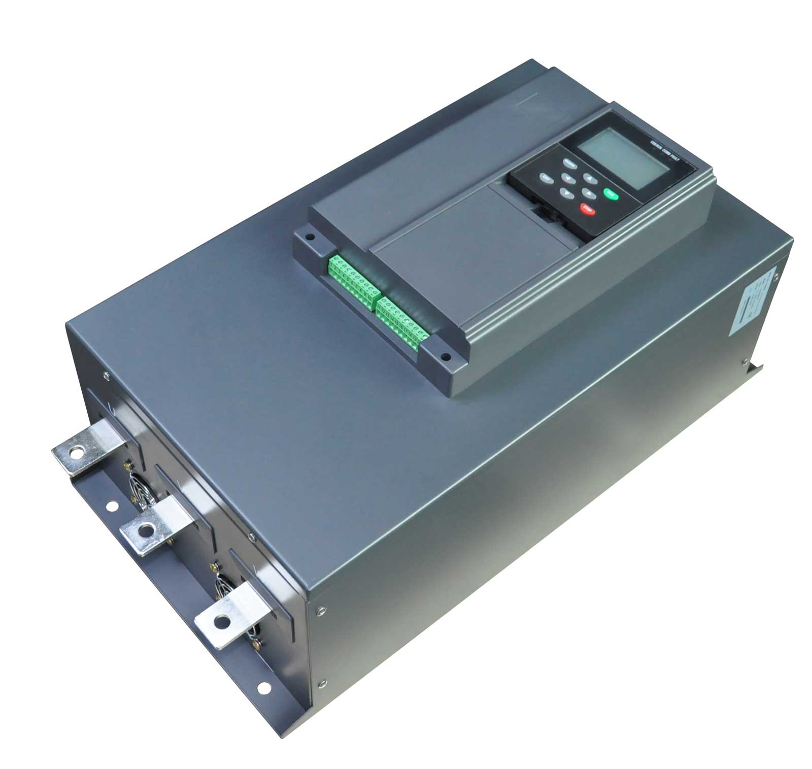
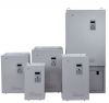
2.1 FST-650L High-Performance Vector Universal Frequency Converter
The flagship solution for large compressor applications:
Application Example: In a 6,000 Nm³/h electronics plant air station, one FST-650L-160G/185PT4 (160kW) controls a variable speed lead compressor, with two fixed-speed 160kW units as lag machines. During night shifts when demand falls to 30% of capacity, the lead machine slows to 45Hz instead of cycling between load and unload—saving 96,000 kWh annually with a payback period of 15 months.
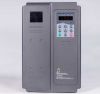
2.2 FST-610 High-Performance Non-Sensory Vector Frequency Converter
For demanding compressor applications requiring fast torque response:
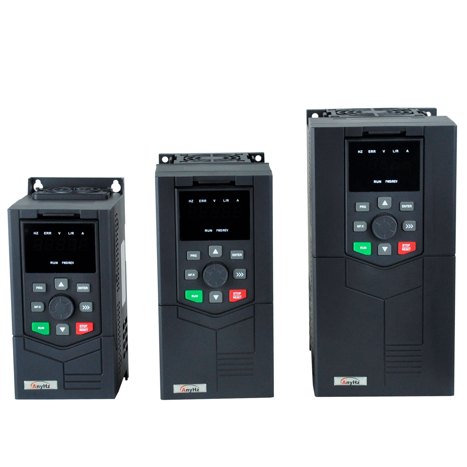
2.3 FST-500 Mini-Type SVC Frequency Inverter
Ideal for small workshop compressors and pneumatic equipment:
-
Power Range: 0.4kW – 7.5kW
-
Compact Design: 40% smaller than standard VFDs, fits directly inside compact compressor enclosures
-
Key Features:
-
Silent operation: 1-16kHz carrier frequency for noise-sensitive workshops
-
Simple parameterization: 15-second quick setup for standard screw compressors
-
Single-phase input options: For small 220V workshop compressors
Section 3: Technical Solution Architecture
3.1 PID Closed-Loop Pressure Control
System Configuration:
-
Pressure Transmitter: Installed at the common header (0-16 bar, 4-20mA output)
-
FST-650L VFD: Compares feedback pressure to setpoint (e.g., 6.5 bar)
-
Modulation Range: 30-100% speed (20-50Hz typical floor to maintain adequate oil circulation in screw compressors)
-
Result: Pressure stability within ±0.1 bar vs. ±0.5 bar with load/unload control
Recommended PID Settings:
-
P (Proportional): 40-80% (faster response for plants with sudden demand surges)
-
I (Integral): 1.0-3.0s
-
D (Derivative): 0-0.2s (optional, for header with multiple consumers)
3.2 Multi-Compressor Cascade Control
AnyHz FST-650L supports intelligent multi-compressor coordination for plants with 2-4 machines:
Three-Compressor Air Station Configuration:
-
Lead Compressor: Variable speed (FST-650L controlled), handles 30-100% of demand modulation
-
Lag Compressor 1: Fixed speed, stages on when lead machine reaches 95% speed for 60 seconds
-
Lag Compressor 2: Fixed speed, stages on during peak demand
-
Rotation: Automatic lead/lag rotation every 168 operating hours to equalize wear
Energy Efficiency Gains:
-
The VFD-controlled lead machine absorbs all demand fluctuation, eliminating load/unload cycles entirely
-
Fixed-speed lag machines run at their optimal full-load efficiency point
-
Overall station efficiency improves 25-35% compared to all-fixed-speed operation
3.3 Combined Dryer & Cooling Fan Integration
Complete system optimization extends beyond the main motor:
-
Refrigerated dryer: Compressor capacity control signal linked to dryer refrigeration cycle
-
Cooling fans: AnyHz FST-500 drives on compressor cooling fans, modulated by discharge temperature
-
Additional savings: 8-12% reduction in auxiliary power consumption
Section 4: Real-World Compressed Air Case Studies
Case Study 1: Automotive Parts Factory – Main Compressor Retrofit
Project: Tier-1 automotive components plant in Suzhou, China
Challenge:
-
1x 132kW screw compressor running load/unload, operating 6,000 hours/year
-
Average load factor only 45% due to fluctuating pneumatic tool demand across three shifts
-
System pressure maintained at 7.0 bar to cover peak moments; actual average requirement 6.2 bar
-
Monthly energy bill: ¥48,000 (approx. $6,700)
Solution: Retrofitted with 1× FST-650L-132G/160PT4 (132kW/160kW) vector VFD with header pressure closed-loop control
Implementation:
-
Installed pressure transmitter at air header (0-10 bar range, 4-20mA)
-
Configured PID control with 6.3 bar setpoint
-
Set minimum frequency 35Hz to guarantee lubrication and cooling at low speed
-
Enabled sleep function for weekend low-demand periods
-
Integrated with plant energy management system via RS485 Modbus
Results (18-Month Operation):
-
Energy reduction: 38% (from 792,000 kWh to 491,000 kWh annually)
-
Cost savings: ¥218,000/year (approx. $30,500) at ¥0.72/kWh
-
Payback period: 13 months
-
Additional benefits:
-
Pressure fluctuation narrowed from ±0.5 bar to ±0.08 bar
-
Eliminated 8-10 unload cycles per hour (each venting ~40 kWh equivalent annually)
-
Airend bearing vibration reduced 35% due to smooth operation
-
Zero motor winding failures since retrofit (previously 1 per 2 years)
Case Study 2: Textile Mill – Multi-Compressor Central Station
Project: Woven fabric manufacturer in Nantong, China
Challenge:
-
3x 75kW compressors: one load/unload machine, one modulation-control machine, one standby
-
Compressors fighting each other: simultaneous load/unload caused pressure swings of 6.0-7.5 bar
-
High maintenance: inlet valves replaced every 8 months; motors rewound twice in 5 years
-
Air leaks inflated by high average pressure: estimated 25% of production lost
Solution: 1× FST-650L-075G/090PT4 (75kW) variable speed retrofit on one unit + cascade control logic for all three machines
Implementation:
-
Designated VFD machine as permanent lead, handling all demand modulation
-
Configured cascade logic: lag machines stage on at 95% speed / stage off at 35% speed
-
Reduced header setpoint from 7.2 bar to 6.4 bar (air tools re-rated)
-
Installed automatic drain valves and leak detection program alongside retrofit
Results:
-
Station energy savings: 33% (from 1,180,000 kWh to 790,000 kWh annually)
-
Pressure stability: ±0.1 bar across all operating conditions
-
Maintenance: Inlet valve replacements eliminated entirely on VFD machine; lag machine maintenance extended to 24-month intervals
-
Air leak reduction: Lower average pressure cut leak volume by 18%, equivalent to recovering one compressor's worth of capacity
-
ROI: 14 months including leak repair program
Case Study 3: Food & Beverage Plant – Hygienic Air System Upgrade
Project: Dairy processing facility in Shandong, China
Challenge:
-
2x 55kW oil-free screw compressors supplying packaging lines and CIP systems
-
Strict requirements: ISO 8573-1 Class 0 air; pressure drops cause filling line stoppages (each stop costs ~¥2,000 in product loss)
-
Original system: one compressor running load/unload, one standby—standby unit could not share load, causing single-point failure risk
Solution: 2× FST-650L-055G/075PT4 (55kW/75kW) with master-slave cascade + dual-header pressure transmitters
Implementation:
-
Both compressors converted to variable speed with alternating lead/lag duty
-
Pressure setpoint 6.5 bar ±0.1 bar; both machines share load proportionally during peak demand
-
Sleep/wake logic synchronized with production schedule (CIP cycles at fixed times)
-
4-20mA pressure signal dual-redundant with automatic failover to local pressure switch control
Results:
-
Energy savings: 29% (from 610,000 kWh to 433,000 kWh annually)
-
Production losses: Filling line air-related stoppages reduced from 6/month to zero
-
Reliability: Dual-VFD redundancy achieved; either machine can carry 100% of average demand alone
-
Compliance: Consistent Class 0 air quality maintained; pressure dew point stabilized at -40°C
-
Investment payback: 17 months including redundant pressure instrumentation
Section 5: AnyHz Frequency Converter Technical Specifications for Compressed Air
FST-650L Compressed Air-Optimized Parameters
| Specification |
Value |
Compressed Air Significance |
|
Input Voltage
|
3-phase 380V ±15%
|
Handles grid fluctuations in industrial parks
|
|
Output Frequency
|
0-500Hz
|
Covers 25-100% compressor speed range
|
|
Overload Capacity
|
150% for 60s, 180% for 10s
|
Handles high breakaway torque of screw airends
|
|
PID Resolution
|
0.01Hz
|
Precise ±0.1 bar pressure control
|
|
Analog Inputs
|
2× 0-10V / 4-20mA
|
Connects to pressure transmitters, temperature sensors
|
|
Digital Inputs
|
5× programmable
|
Lag machine staging signals, emergency stop, remote start
|
|
Relay Outputs
|
2× programmable
|
Compressor run status, fault alarm, lag staging
|
|
Communication
|
RS485 (Modbus RTU)
|
Plant energy management integration standard
|
|
Protection Class
|
IP20 (standard)
|
Suitable for compressor rooms with dust/oil mist
|
|
Ambient Temperature
|
-10°C to +40°C
|
Operates in unconditioned plant rooms
|
|
EMC Filter
|
Built-in C3 filter
|
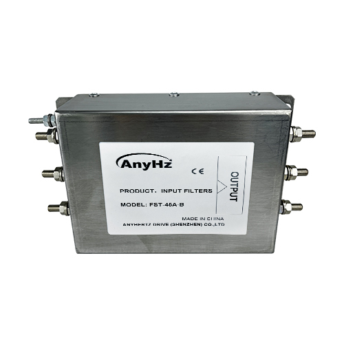
Meets industrial facility EMC requirements
|
FST-500 Mini VFD Specifications
| Specification |
Value |
Compressed Air Significance |
|
Power Range
|
0.4kW – 7.5kW
|
Matches small workshop compressors and pneumatic auxiliaries
|
|
Dimensions
|
142×86×118mm (0.75kW)
|
Fits inside compact compressor enclosures
|
|
Carrier Frequency
|
1-16kHz adjustable
|
Silent operation in noise-sensitive workshops
|
|
V/f Curves
|
4 preset + 1 custom
|
Optimized for screw compressor torque curves
|
|
Installation
|
DIN rail mount
|
Quick retrofit of existing control panels
|
Section 6: Compressed Air VFD Selection Guide
Step 1: Determine Compressor Type
| Compressor Type |
Load Characteristics |
Recommended Control Mode |
|
Screw (fixed displacement)
|
Air output ∝ speed
|
Vector control with 30% minimum speed limit
|
|
Centrifugal
|
Power ∝ speed³
|
Vector control, surge protection curve essential
|
|
Piston/reciprocating
|
Pulsating torque
|
Vector control with torque smoothing
|
|
Scroll
|
Smooth torque
|
Standard V/f with quadratic curve
|
Step 2: Calculate Power Requirements
-
Compressor shaft power: P = (Q × p₁ × k) / (η × 1000) [kW] (consult airend manufacturer curve)
-
Safety margin: Select VFD with ≥15% margin above motor rated power (screw compressors demand sustained high torque at low speed)
-
Minimum speed limit: Set ≥30Hz (typically) to maintain oil injection and cooling airflow in screw machines
Step 3: Select Environmental Protection
| Environment |
Protection Requirement |
AnyHz Solution |
|
Clean compressor room
|
IP20
|
Standard FST-650L
|
|
Dusty workshop
|
IP20
|
FST-650L with sealed enclosure + filtered cooling air
|
|
High humidity (>90%RH)
|
Conformal coating
|
FST-650L option
|
|
Corrosive atmosphere
|
Conformal coating + IP54
|
FST-650L in sealed cabinet
|
Step 4: Specify Control Features
-
Basic pressure control: FST-650L with header pressure transmitter
-
Multi-compressor station: FST-650L with built-in cascade logic
-
Remote monitoring: FST-650L with RS485 Modbus + AnyHz IoT gateway (optional 4G)
-
Demand forecasting: Optional AnyHz AI module linking VFD to production schedule
Section 7: Installation Best Practices for Compressed Air
7.1 Electrical Installation
-
Input protection: Class J fuses or circuit breaker at 1.5× VFD rating
-
Output filtering: For motor cable runs >100m, use AnyHz output reactor to prevent voltage reflection (critical for long runs to roof-mounted compressor rooms)
-
Grounding: Dedicated PE bus, ground impedance <0.1Ω to prevent EMI in pressure sensor circuits
-
Bypass cabinet (optional): For critical applications, configure manual variable/fixed frequency bypass to allow continued operation during VFD maintenance
7.2 Sensor Wiring
-
4-20mA pressure signal: Shielded twisted pair, grounded at VFD end only; transmitter mounted at common header, not at compressor discharge
-
Temperature sensors: PT100 or 4-20mA discharge temperature monitoring for low-speed protection
-
Safety chain: Emergency stop and high-discharge-temperature trip must be hardwired, independent of VFD control
7.3 Parameter Configuration for Compressor Application
Essential FST-650L settings for pressure closed-loop control:
| Parameter |
Setting |
Description |
|
F0.03
|
8
|
Enable PID function
|
|
F0.10
|
50.00
|
Maximum frequency
|
|
F0.17
|
10.0
|
Acceleration time (prevents pressure overshoot)
|
|
F0.18
|
15.0
|
Deceleration time (prevents backflow through check valve)
|
|
F4.18
|
2.0
|
CCI simulation curve selection
|
|
FA.00
|
0
|
PID given source (keypad/analog)
|
|
FA.01
|
63.0%
|
PID setpoint (6.3 bar)
|
|
FA.02
|
1
|
PID feedback (4-20mA pressure)
|
|
FA.05/FA.06/FA.07
|
60.0 / 2.0 / 0.0
|
PID P / I / D tuning
|
|
F8.49
|
15.0
|
Wake-up frequency (on pressure drop)
|
|
F8.51
|
10.0
|
Sleep frequency (below this, enter sleep)
|
Section 8: Troubleshooting Common Compressor VFD Issues
| Symptom |
Probable Cause |
AnyHz Solution |
|
Motor overheating at low speed
|
Insufficient cooling airflow at <30Hz
|
Raise minimum frequency to 35Hz; enable automatic carrier adjustment; add external shaft-mounted fan
|
|
Pressure oscillation
|
PID tuning too aggressive
|
Reduce P gain to 40%, increase I time; use FST-650L PID auto-tune
|
|
VFD trips on overvoltage
|
Regeneration during rapid decel with pressurized line
|
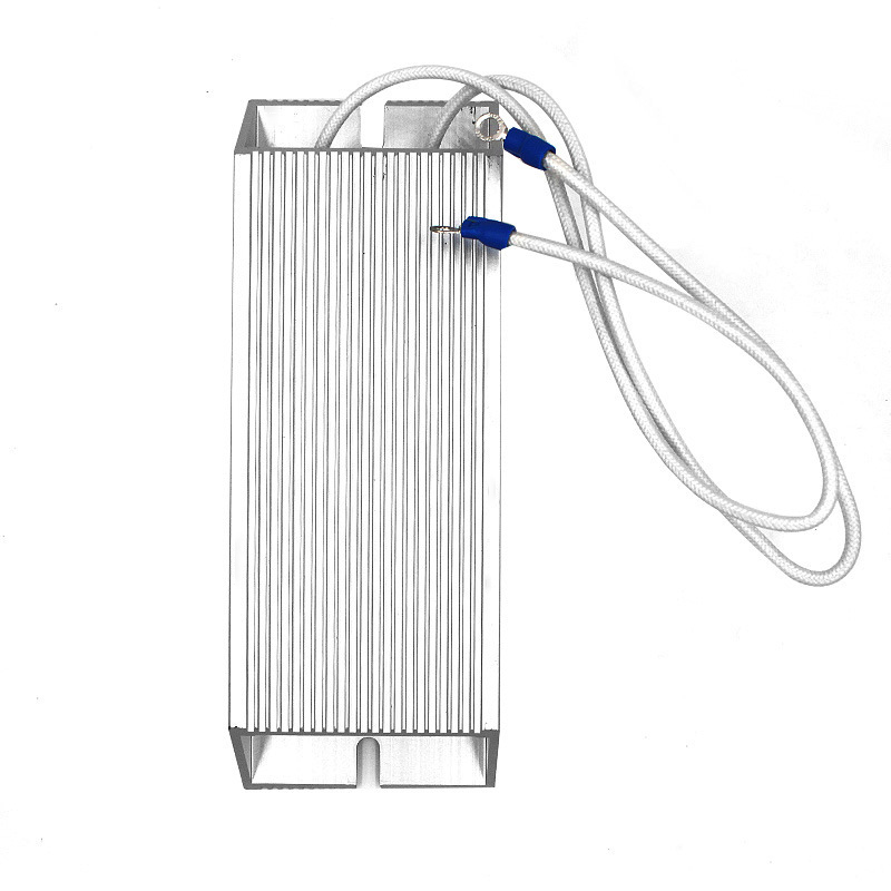
Extend deceleration time (F0.18); install AnyHz braking unit
|
|
Oil carryover in air
|
Prolonged low-speed operation reducing oil separation efficiency
|
Set minimum speed ≥35Hz; add timer to force full-speed run 10 min every 4 hours
|
|
Pressure sensor drift
|
Condensation in transmitter lines
|
Install transmitter with condensate trap; use 3-valve manifold for isolation
|
|
Cascade hunting (lag machine cycling on/off)
|
Hysteresis band too narrow
|
Widen staging thresholds: ON at 95%, OFF at 30%; add 120s time delay between staging events
|
|
Communication loss with plant EMS
|
Modbus address/baud conflict
|
Verify FD.02 (address) and FD.00 (baud rate); use shielded RS485 cable, terminate both ends
|
Section 9: Energy Savings Calculation & ROI Analysis
Example: 90kW Screw Compressor with FST-650L
Baseline (Fixed Speed Load/Unload, 45% Average Load Factor):
-
Annual operating hours: 6,000 h
-
Loaded energy: 6,000 h × 45% × 90 kW × 1.05 (motor/service factor) = 255,150 kWh
-
Unloaded energy: 6,000 h × 55% × 90 kW × 0.35 (unloaded draw) = 103,950 kWh
-
Total baseline: 359,100 kWh/year
With AnyHz FST-650L (Speed Modulation):
-
Average speed at 45% air demand: ~78% (screw output ∝ speed)
-
Annual energy: 359,100 × 0.62 (overall modulation efficiency gain) ≈ 222,600 kWh
-
Annual savings: 136,500 kWh (38%)
-
Cost savings at ¥0.72/kWh: ¥98,280 (approx. $13,700)/year
-
Investment (VFD + transmitter + installation): ¥78,000
-
Simple payback: 9.5 months
Section 10: Future Trends – Smart Compressed Air with AnyHz
Compressed Air 4.0 Integration
AnyHz is developing next-generation frequency converter solutions for smart air systems:
-
IoT connectivity: Optional 4G/WiFi module for remote multi-station monitoring and pressure profiling
-
Predictive maintenance: AI algorithms analyze current signatures to predict airend bearing wear and oil degradation 4-6 weeks in advance
-
Digital twin integration: VFD operating data synchronized with compressed air system modeling to continuously optimize setpoints
-
Demand-side linkage: Machine learning correlates VFD data with production schedules to pre-position system pressure before demand surges
Conclusion: Why Choose AnyHz for Compressed Air Frequency Converters
✅ Proven energy savings: 25-45% validated across 500+ compressed air installations
✅ Compressed air optimized: PID pressure control, multi-compressor cascade, sleep/wake, dry-run protection
✅ Harsh environment ready: Conformal coating options, -10°C to +40°C operation, IP54 enclosures for dusty plant rooms
✅ Expert support: Application engineers with 10+ years of compressed air system experience
✅ Cost-effective: 20-30% lower cost than tier-1 brands with equivalent performance
Ready to cut your compressed air energy costs? Contact AnyHz Drive for a free compressed air system audit and frequency converter selection consultation.
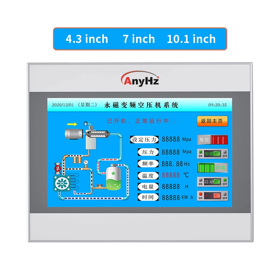
About Anyhertz Drive (Shenzhen) Co., Ltd. With 20 years of R&D experience and 156+ patents, Anyhertz Drive specializes in variable frequency drives, HMI touch screens, and complete industrial automation solutions serving textile, water treatment, HVAC, woodworking, mining, and general manufacturing industries worldwide.



 Contact Us


