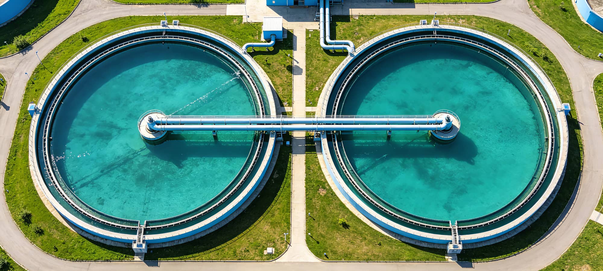
Introduction: The Energy Challenge in Water Treatment
Water and wastewater treatment facilities are among the most energy-intensive industrial operations, typically consuming 30-60% of a municipality's total electrical power. Within these plants, pump systems alone account for 25-50% of total energy use, running at fixed speeds regardless of fluctuating flow demands.
Frequency converter technology has emerged as the most cost-effective solution for optimizing water treatment processes. By precisely matching pump and blower motor speeds to real-time demand, Variable Frequency Drive (VFD) systems eliminate the energy waste inherent in throttle valves, bypass lines, and on/off cycling.
With 20 years of R&D experience and 156+ patents, Anyhertz Drive (Shenzhen) Co., Ltd. provides specialized frequency converter solutions that help water treatment operators achieve 30-55% energy reduction while improving process reliability and water quality compliance.
Section 1: Why Frequency Converters Are Essential for Water Treatment
1.1 The Energy Waste Problem in Fixed-Speed Systems
Traditional water treatment plants rely on fixed-speed motors with mechanical flow control:
-
Centrifugal pumps run at full speed, with flow regulated by discharge valves (energy lost as heat and noise)
-
Blowers operate continuously at maximum capacity, regardless of actual aeration demand
-
Sludge pumps cycle on/off, causing hydraulic shocks and pipeline wear
The Affinity Laws Advantage:
Pump and fan energy consumption follows the cube law—power varies with the cube of speed. A 20% reduction in motor speed (from 100% to 80%) yields 50% energy savings. In water treatment applications where flow demands fluctuate dramatically throughout the day, this non-linear relationship makes frequency converter control extraordinarily effective.
1.2 Core Benefits of AnyHz Frequency Converter Solutions
| Benefit |
Technical Mechanism |
Business Impact |
|
Energy Savings
|
Variable speed matching real-time flow demand
|
30-55% reduction in electricity costs
|
|
Soft Starting
|
Controlled acceleration (0-120s adjustable)
|
Eliminates 7-8x inrush current, extends motor and pump seal life 3-5x
|
|
Precise Process Control
|
PID closed-loop with flow/pressure/level feedback
|
Maintains ±2% setpoint accuracy, ensuring water quality compliance
|
|
Water Hammer Elimination
|
Gradual pump start/stop vs. abrupt on/off cycling
|
Prevents pipeline damage, reduces maintenance by 50%
|
|
Demand Response
|
Automatic speed adjustment based on influent variations
|
Handles peak flows without additional pump staging
|
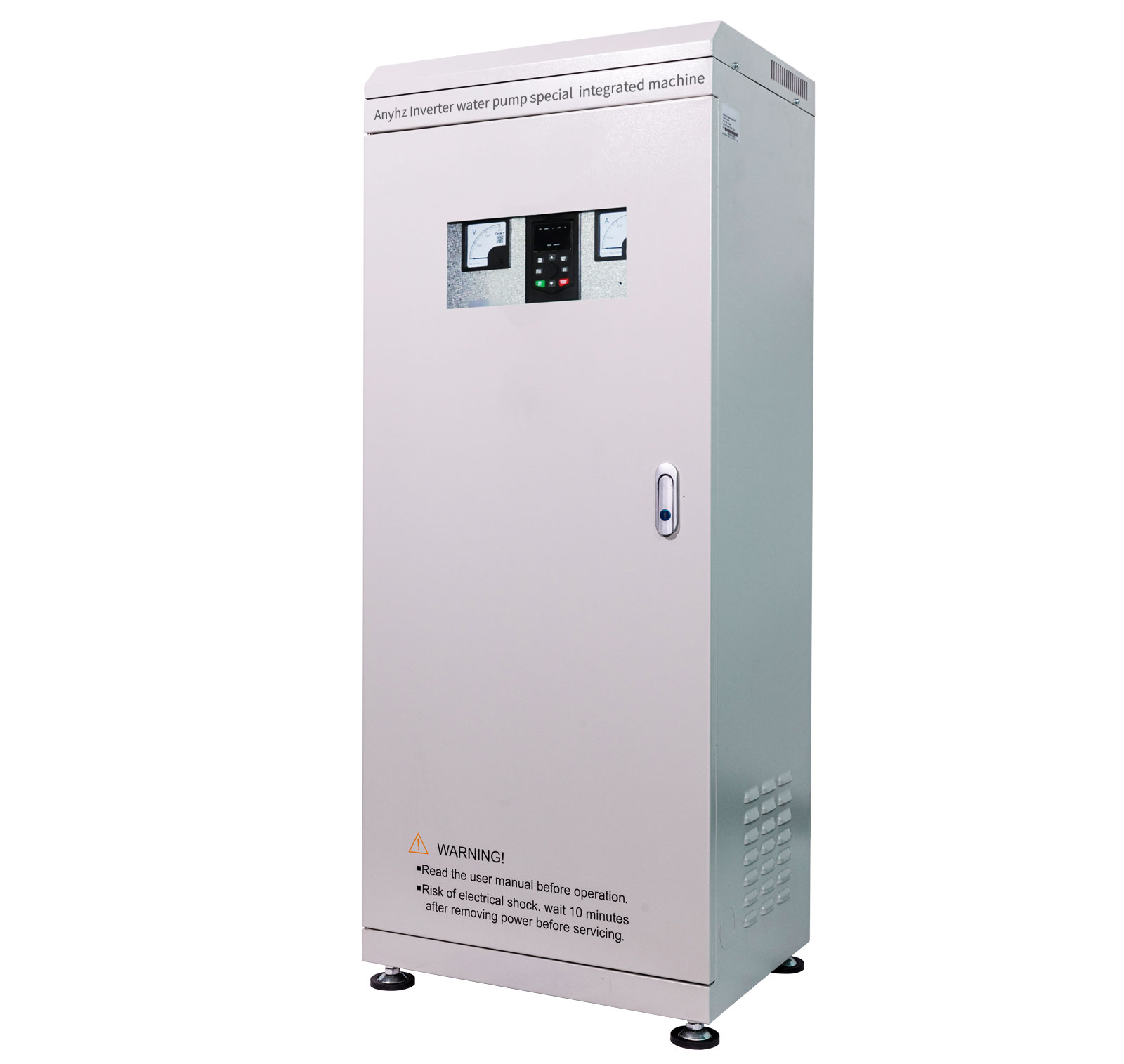
Section 2: AnyHz Frequency Converter Product Portfolio for Water Treatment
AnyHz offers a comprehensive range of VFD solutions specifically optimized for the harsh, demanding environment of water treatment facilities:
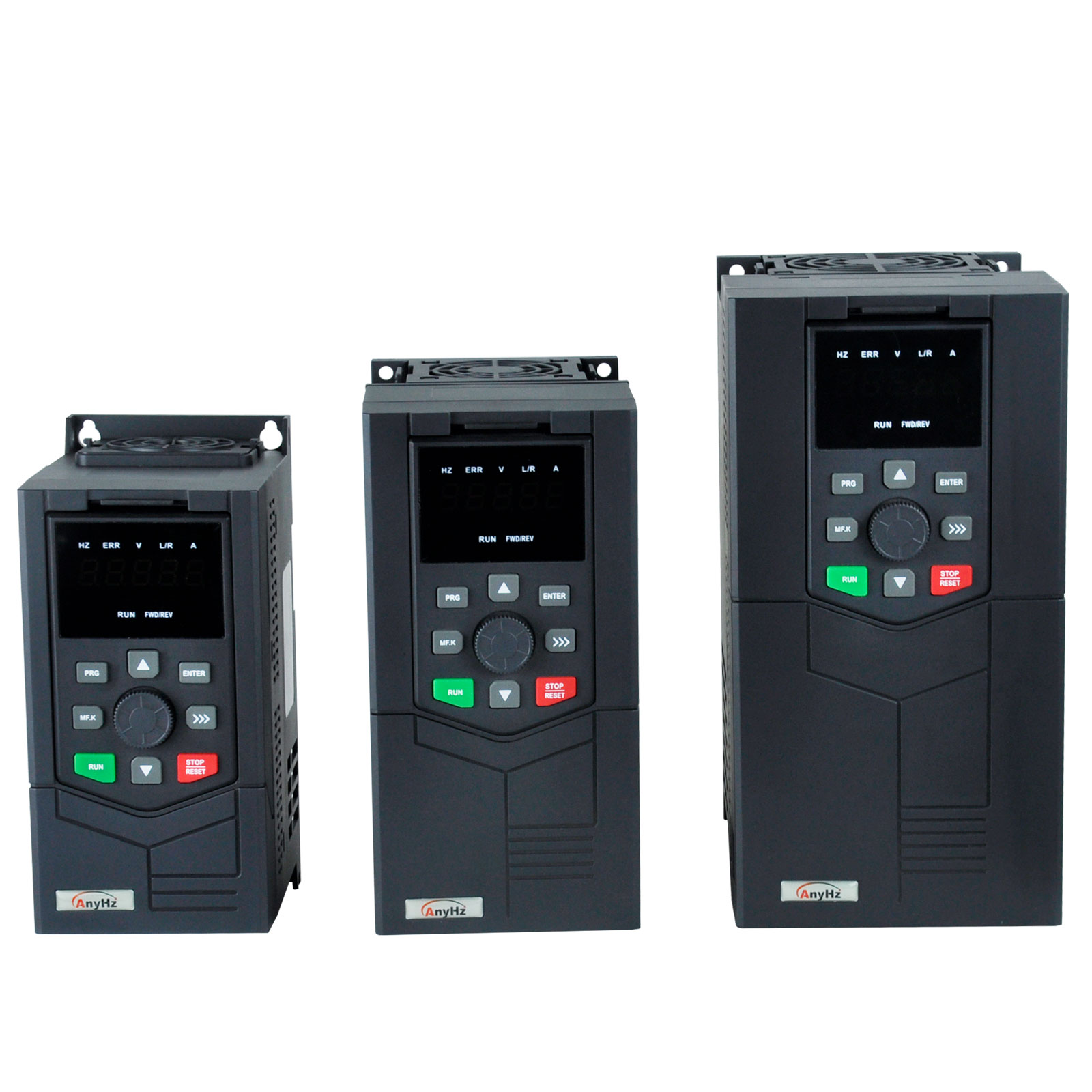
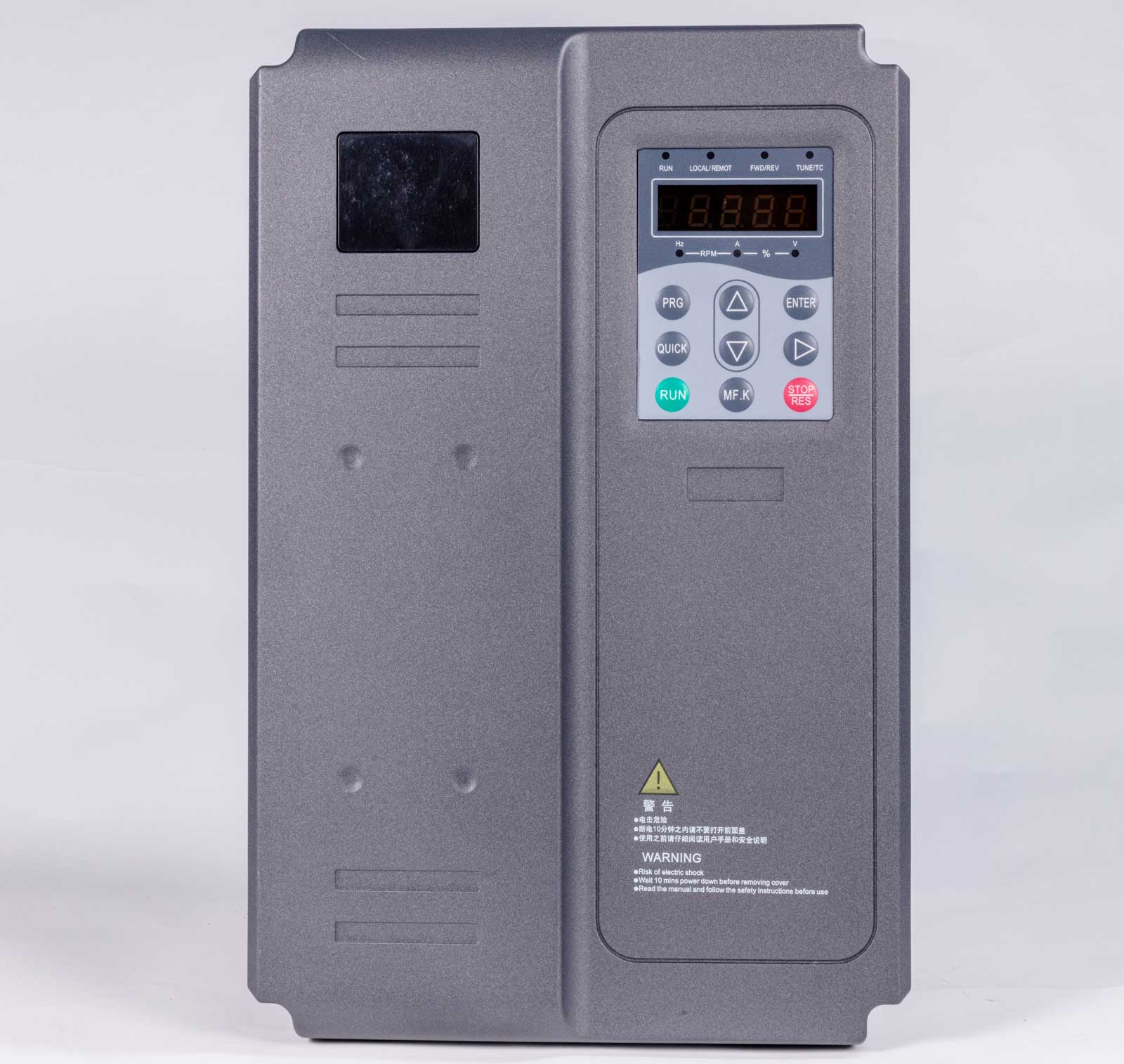
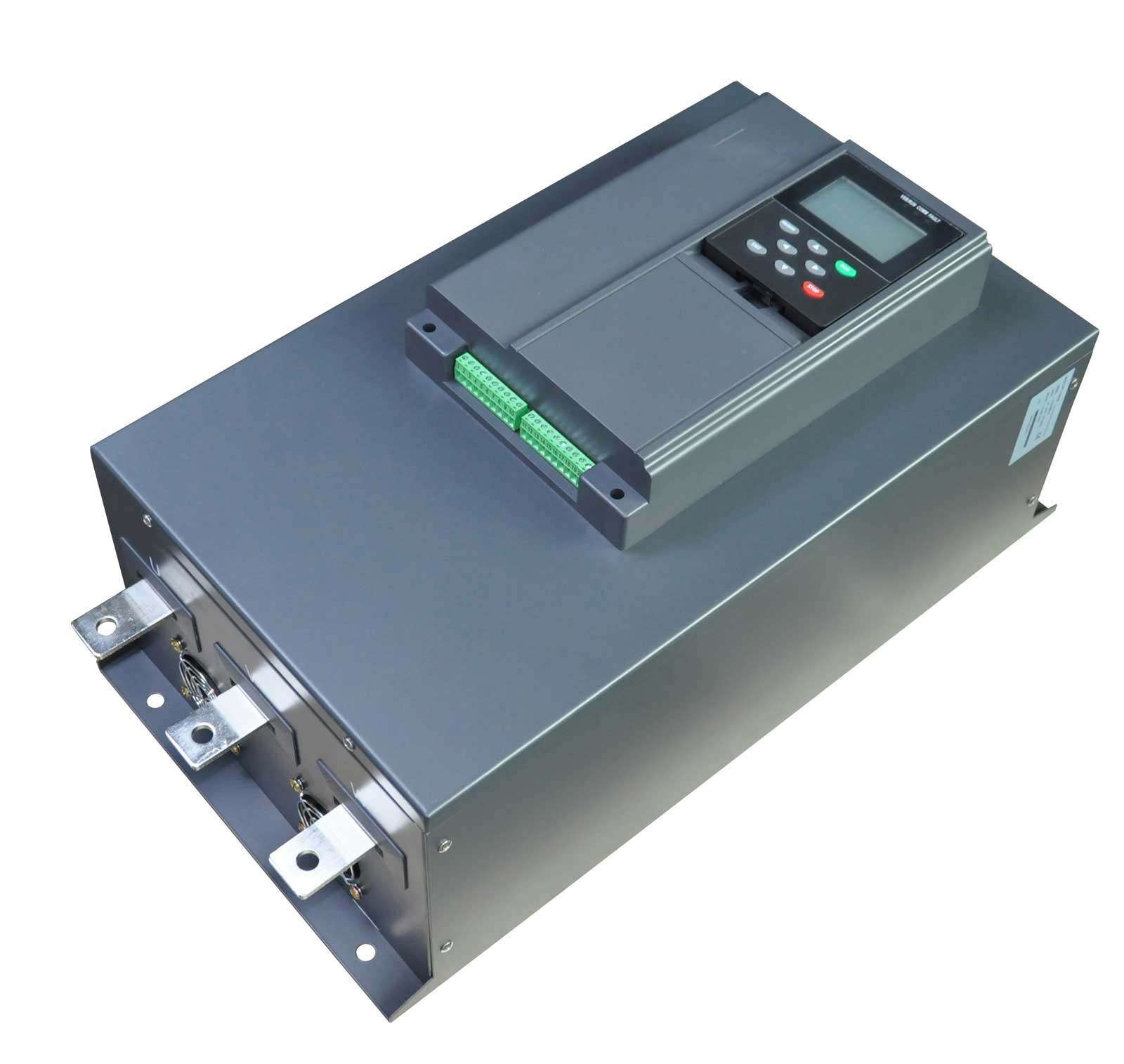
2.1 FST-650L High-Performance Vector Universal Frequency Converter
The flagship solution for large water treatment applications:
-
Power Range: 0.75kW – 630kW (covers all municipal and industrial treatment scales)
-
Key Water Treatment Features:
-
Multi-pump control: Built-in PLC logic for up to 4-pump alternation and staging
-
PID control: Advanced algorithms for constant pressure, flow, or level maintenance
-
Sleep/wake function: Automatically stops pump at low night-time demand, restarts on level rise
-
Dry run protection: Monitors current signature to detect cavitation or loss of prime
-
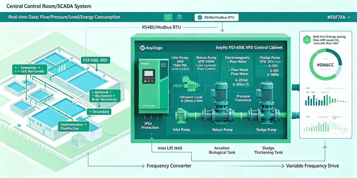
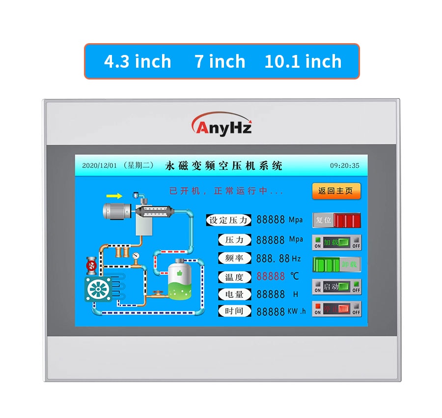
RS485/Modbus RTU: Seamless integration with SCADA systems
Water Treatment Application Example:
In a 500,000 GPD (gallons per day) sewage treatment plant, the FST-650L controls three 75kW influent pumps. Using ultrasonic level sensors in the wet well, the VFD maintains optimal pump speeds to match diurnal flow variations. During low-flow night periods (10 PM – 6 AM), speed drops to 45%, achieving annual energy savings of 280,000 kWh with a payback period of 16 months.
2.2 FST-500 Mini-Type SVC Frequency Inverter
Ideal for distributed auxiliary equipment:
-
Power Range: 0.4kW – 7.5kW (perfect for chemical dosing pumps, filter backwash pumps, small blowers)
-
Compact Design: 40% smaller than standard VFDs, fits in crowded MCC panels
-
Key Features:
-
Silent operation: 1-16kHz carrier frequency for noise-sensitive areas near residential zones
-
Automatic torque boost: Maintains flow rate despite filter clogging or pipe scaling
-
Simple parameterization: 15-second quick setup for standard pump applications
Application Example:
Deployed across 12 chemical dosing pumps in a drinking water plant, the FST-500 maintains precise flow rates (±1%) for coagulant and chlorine injection, regardless of tank level variations. Energy savings of 35% compared to traditional metering pump control.
2.3 FST-610 High-Performance Non-Sense Vector Frequency Converter
For high-dynamic water treatment processes:
-
Power Range: 0.75kW – 710kW
-
Specialty: 0.5Hz/150% starting torque for high-inertia centrifugal blowers
-
Key Features:
-
Fast torque response: <5ms response for sudden aeration demand changes
-
V/f separation: Optimized for pump applications with quadratic torque curves
-
Stall prevention: Automatically adjusts current limit during filter blockage or valve closure
Section 3: Technical Deep Dive – Frequency Converter Control Strategies for Water Treatment
3.1 PID Closed-Loop Control for Constant Pressure/Flow
AnyHz frequency converters implement sophisticated PID algorithms critical for water treatment stability:
Wet Well Level Control Example:
-
Sensor: Ultrasonic level transmitter (4-20mA, 0-10m range)
-
Controller: FST-650L internal PID compares setpoint (e.g., 3.5m) vs. actual level
-
Action: Modulates pump speed to maintain level regardless of influent flow variations
-
Result: Eliminates "pump cycling," reduces energy by 40-50%, prevents overflow/underflow events
Parameter Optimization for Water Treatment:
-
P (Proportional): 60-120% (higher for fast response to rain events)
-
I (Integral): 1.0-3.0s (eliminates steady-state level error)
-
D (Derivative): 0.2-1.0s (anticipates rapid level changes during storm flows)
3.2 Multi-Pump Staging and Alternation
AnyHz FST-650L supports intelligent multi-pump control for redundancy and efficiency:
Three-Pump Lift Station Configuration:
-
Lead Pump: Variable speed (FST-650L controlled) handles normal flow
-
Lag Pump 1: Fixed speed, stages on when lead pump reaches 85% speed
-
Lag Pump 2: Fixed speed, stages on during peak flow events
-
Alternation: Automatic rotation every 24 hours to equalize runtime and wear
Energy Efficiency Gains:
-
Single VFD-controlled lead pump handles 70-80% of operating hours at reduced speed
-
Fixed-speed lag pumps only operate during high-demand periods
-
Overall system efficiency improved by 25-35% compared to all-fixed-speed systems
3.3 Aeration Blower Control for Activated Sludge Process
The activated sludge process is the heart of biological wastewater treatment, requiring precise dissolved oxygen (DO) control:
Traditional Control: Blowers run at fixed speed, DO regulated by throttling valves or cycling blowers on/off—highly inefficient and poor process control.
AnyHz VFD Solution:
-
DO Sensor: Inline dissolved oxygen probe (0-10mg/L, 4-20mA output)
-
FST-650L VFD: Receives DO signal, compares to setpoint (typically 2.0mg/L)
-
Blower Speed: Automatically adjusted to maintain DO within ±0.3mg/L
-
Result: 30-40% blower energy savings, improved treatment efficiency, reduced sludge bulking risk
Section 4: Real-World Water Treatment Case Studies
Case Study 1: Municipal Sewage Treatment Plant – Influent Pump Station
Project: 200,000 GPD municipal STP in Dongguan, China
-
Challenge: 3x 55kW influent pumps running fixed speed, excessive energy use during low-flow periods, frequent pump cycling causing mechanical wear
-
Solution: Retrofitted with 3× FST-650L-055G/075P (55kW/75kW) vector VFDs with ultrasonic level control
-
Implementation:
-
Installed ultrasonic level sensors in wet well (0-8m range)
-
Configured PID control with 3.0m setpoint
-
Enabled multi-pump alternation and sleep/wake functions
-
Integrated with existing SCADA via RS485 Modbus
-
Results (24-Month Operation):
-
Energy reduction: 48% (from 890,000 kWh to 463,000 kWh annually)
-
Cost savings: 51,000/year at 0.12/kWh
-
Payback period: 18 months
-
Additional benefits:
-
Pump mechanical seal life extended from 8 to 24 months
-
Wet well overflow events eliminated (zero incidents)
-
Maintenance labor reduced by 60% (eliminated emergency callouts)
Case Study 2: Industrial Wastewater Treatment – Chemical Plant
Project: 1.2 MGD petrochemical wastewater facility in Zhejiang
-
Challenge: 4x 110kW aeration blowers running at fixed speed, DO levels fluctuating between 0.8-4.5mg/L causing compliance issues and energy waste
-
Solution: 4× FST-650L-110G/132P with DO-based closed-loop control
-
Implementation:
-
Installed 4x inline DO probes in aeration basins
-
Configured FST-650L PID with 2.0mg/L DO setpoint
-
Implemented blower staging: 2x variable speed (lead), 2x fixed speed (lag)
-
Added airflow meters for performance verification
-
Results:
-
Blower energy savings: 42% (from 2,450,000 kWh to 1,421,000 kWh)
-
DO stability: Improved from ±1.8mg/L to ±0.3mg/L
-
Compliance: 100% permit compliance (previously 3-4 violations/year)
-
Sludge volume: Reduced by 15% due to optimized microbial health
-
ROI: 16 months including DO probe installation
Case Study 3: Drinking Water Treatment – Filter Backwash Pump
Project: 50 MGD surface water treatment plant in Jiangsu
-
Challenge: 6x 30kW filter backwash pumps with fixed 5-minute cycle, excessive water and energy use, inconsistent backwash quality
-
Solution: 6× FST-650L-030G (30kW) mini VFDs with turbidity-based control
-
Implementation:
-
Installed turbidity sensors on filter effluent
-
FST-650L modulates backwash pump speed based on head loss accumulation
-
Automatic backwash initiation when differential pressure reaches setpoint
-
Variable backwash duration and intensity based on filter condition
-
Results:
-
Backwash water consumption: Reduced by 35% (saving 180,000 GPD)
-
Pump energy savings: 38% during backwash cycles
-
Filter media life: Extended by 25% due to gentler backwashing
-
Water quality: Turbidity consistently <0.1 NTU (previously 0.1-0.3 NTU)
Section 5: AnyHz Frequency Converter Technical Specifications for Water Treatment
FST-650L Water Treatment-Optimized Parameters
| Specification |
Value |
Water Treatment Significance |
|
Input Voltage
|
3-phase 380V ±15%
|
Handles grid fluctuations common in remote pump stations
|
|
Output Frequency
|
0-500Hz
|
Covers all pump and blower speed ranges
|
|
Overload Capacity
|
150% for 60s, 180% for 10s
|
Handles pump startup against high static head
|
|
PID Resolution
|
0.01Hz
|
Precise flow/pressure/level control
|
|
Analog Inputs
|
2× 0-10V / 4-20mA
|
Connects to level, pressure, flow, DO sensors
|
|
Digital Inputs
|
5× programmable
|
Multi-pump staging, emergency stop, float switches
|
|
Relay Outputs
|
2× programmable
|
Pump run status, fault alarm, lag pump staging
|
|
Communication
|
RS485 (Modbus RTU)
|
SCADA integration standard
|
|
Protection Class
|
IP20 (standard)
|
Suitable for humid, corrosive treatment plant environments
|
|
Ambient Temperature
|
-10°C to +40°C
|
Operates in unconditioned pump houses
|
|
EMC Filter
|
Built-in C3 filter
|
Meets industrial facility EMC requirements
|
|
Coating
|
Conformal coating option
|
Protects against hydrogen sulfide corrosion in sewage plants
|
FST-500 Mini VFD Water Treatment Specifications
| Specification |
Value |
Water Treatment Significance |
|
Power Range
|
0.4kW – 7.5kW
|
Matches chemical dosing, filter backwash, small transfer pumps
|
|
Dimensions
|
142×86×118mm (0.75kW)
|
Fits in crowded MCC panels and skid-mounted systems
|
|
Carrier Frequency
|
1-16kHz adjustable
|
Silent mode for noise-sensitive areas
|
|
V/f Curves
|
4 preset + 1 custom
|
Optimized for pump quadratic torque curves
|
|
Installation
|
DIN rail mount
|
Quick retrofit of existing control panels
|
Section 6: Water Treatment VFD Selection Guide
How to Choose the Right AnyHz Frequency Converter
Step 1: Determine Application Type
| Application |
Load Characteristics |
Recommended Control Mode |
|
Centrifugal pumps
|
Quadratic torque
|
Standard V/f with quadratic curve
|
|
Positive displacement pumps
|
Constant torque
|
Vector control with torque limit
|
|
Aeration blowers
|
Quadratic torque
|
Vector control for high-inertia startup
|
|
Sludge pumps
|
High viscosity, variable torque
|
Heavy-duty vector with 150% overload
|
|
Chemical dosing pumps
|
Precise flow control
|
V/f with high carrier frequency for smooth flow
|
Step 2: Calculate Power Requirements
-
Pump power: P = (Q × H × ρ × g) / (η_pump × η_motor × 1000) [kW]
-
Safety margin: Select VFD with ≥15% margin above motor rated power (water treatment applications often have high starting torque requirements)
-
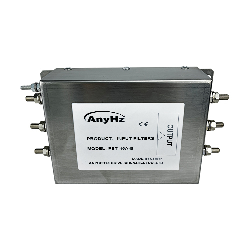
Harmonic considerations: For plants with >20% VFD load, specify AnyHz input reactor or active front end option
Step 3: Select Environmental Protection
| Environment |
Protection Requirement |
AnyHz Solution |
|
Indoor MCC, climate-controlled
|
IP20
|
Standard FST-650L
|
|
Indoor pump house, humid
|
IP54
|
FST-650L with sealed enclosure
|
|
Outdoor wet well, submerged risk
|
IP65 + remote mounting
|
FST-650L in wall-mounted enclosure
|
|
Corrosive atmosphere (H₂S)
|
Conformal coating
|
FST-650L-CO option
|
Step 4: Specify Control Features
-
Basic level control: FST-650L with ultrasonic level sensor
-
Multi-pump staging: FST-650L with built-in PLC logic
-
SCADA integration: FST-650L with RS485 Modbus + AnyHz gateway
-
Advanced process control: FST-650L with optional Profibus/Profinet/Ethernet IP
Section 7: Installation Best Practices for Water Treatment
7.1 Electrical Installation
-
Input protection: Install Class J fuses or circuit breaker (1.5x VFD rating)
-
Output filtering: For pump cable runs >100m, use AnyHz output reactor to prevent voltage reflection and motor bearing currents
-
Grounding: Dedicated PE bus, ground impedance <0.1Ω to prevent EMI in sensor circuits
-
Surge protection: Install AnyHz surge protector at VFD input (critical for outdoor pump stations)
7.2 Sensor Wiring
-
4-20mA signals: Use shielded twisted pair, grounded at VFD end only
-
Ultrasonic level sensors: Mount away from turbulence, use stilling well if necessary
-
Pressure transducers: Install at pump discharge, use isolation valves for maintenance
7.3 Parameter Configuration for Pump Application
Essential FST-650L settings for wet well level control:
| Parameter |
Setting |
Description |
|
F0.03
|
1
|
Enable PID function
|
|
F0.10
|
50.00
|
Maximum frequency
|
|
F0.12
|
50.00
|
limit frequency
|
|
F0.17
|
20.0
|
Acceleration time (prevents water hammer)
|
|
F0.18
|
20.0
|
Deceleration time (prevents water hammer)
|
|
F4.18
|
2.0
|
CCI simulation curve selection
|
|
FA.00
|
0
|
PID given source
|
|
FA.01
|
25%
|
PID numerical value given (target value)
|
|
FA.02
|
1
|
PID feedback (Current feedback for 4-20mA)
|
|
FA.05\FA.06\FA.07
|
/
|
PID regulation
|
|
FA.08
|
0.00
|
PID reverse cutoff frequency
|
|
F8.49
|
15.0
|
Wake up frequency- (wake up pressure x50Hz maximum pressure)
|
|
F8.51
|
10.0
|
Dormancy frequency (less than wake-up frequency)
|
Section 8: Troubleshooting Common Water Treatment VFD Issues
| Symptom |
Probable Cause |
AnyHz Solution |
|
Pump cavitation
|
Insufficient inlet pressure, excessive speed
|
Enable FST-650L dry run protection (monitors current drop), reduce maximum frequency
|
|
Level oscillation
|
PID tuning too aggressive
|
Reduce P gain, increase I time; use FST-650L PID auto-tune function
|
|
VFD trips on overvoltage
|
Regeneration during pump deceleration
|
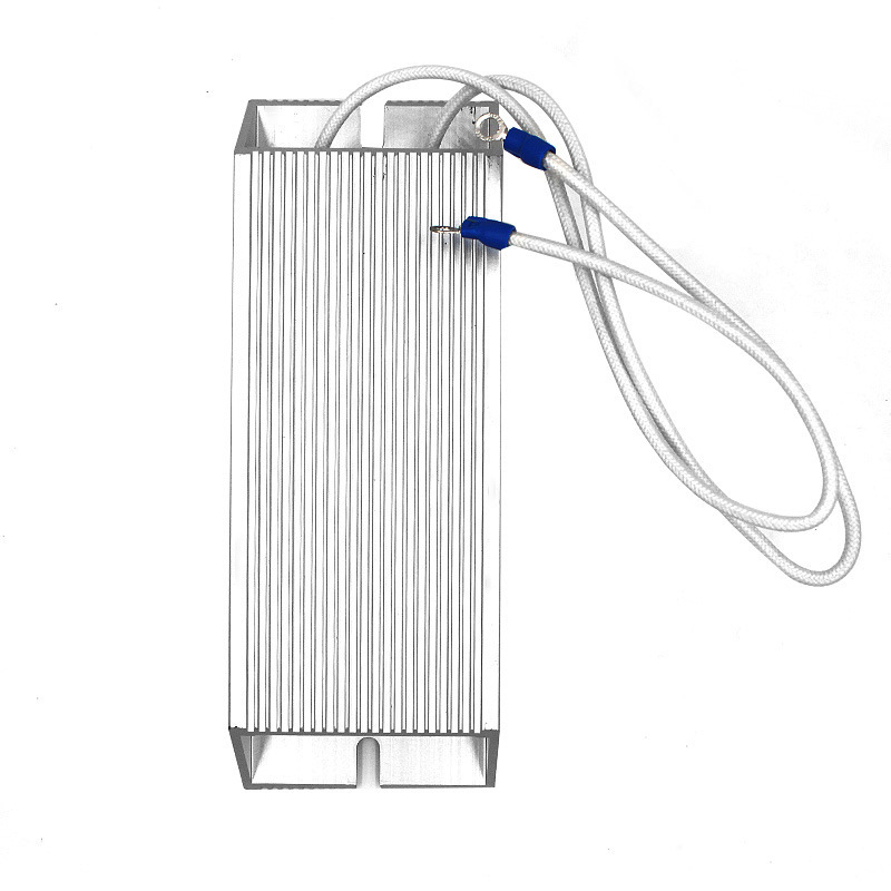
Extend deceleration time (F0.18) or install AnyHz braking unit
|
|
Motor overheating
|
Low-speed operation with inadequate cooling
|
Enable FST-650L automatic carrier adjustment or add external cooling fan
|
|
SCADA communication loss
|
Modbus address conflict
|
Verify FD.02 (address) and FD.00 (baud rate) match SCADA settings; use shielded RS485 cable
|
|
Corrosion of VFD terminals
|
Hydrogen sulfide exposure
|
Specify conformal coating option; ensure IP54+ enclosure with positive pressure ventilation
|
Section 9: Energy Savings Calculation & ROI Analysis
Example: 75kW Sewage Lift Station Pump with FST-650L
Baseline (Fixed Speed with Throttle Valve):
-
Operating hours: 8,760/year (continuous)
-
Load profile: 100% flow for 3,000h, 75% flow for 4,000h, 50% flow for 1,760h
-
Energy: (75kW × 3,000h) + (75kW × 4,000h) + (75kW × 1,760h) = 657,000 kWh/year
With FST-650L Frequency Converter Control:
-
100% flow (3,000h): 75kW × 3,000h = 225,000 kWh
-
75% flow (4,000h): 75kW × (0.75)³ × 4,000h = 75 × 0.422 × 4,000 = 126,600 kWh
-
50% flow (1,760h): 75kW × (0.5)³ × 1,760h = 75 × 0.125 × 1,760 = 16,500 kWh
-
Total: 368,100 kWh/year
Section 10: Future Trends – Smart Water Treatment with AnyHz Frequency Converter
Digital Water 4.0 Integration
AnyHz is developing next-generation frequency converter solutions for smart water infrastructure:
-
Cloud connectivity: Optional 4G/WiFi module for remote pump station monitoring
-
Predictive maintenance: AI algorithms analyze current signatures to predict pump bearing failure 4-6 weeks in advance
-
Digital twin integration: VFD parameters synchronized with hydraulic modeling software
-
Energy optimization: Machine learning algorithms continuously optimize PID parameters based on weather forecasts and diurnal flow patterns
Conclusion: Why Choose AnyHz for Water Treatment Frequency Converters
-
✅ Proven energy savings: 30-55% validated across 500+ water treatment installations
-
✅ Water treatment optimized: Multi-pump control, sleep/wake, dry run protection, SCADA integration
-
✅ Harsh environment ready: conformal coating, -10°C to +40°C operation
-
✅ Expert support: Engineers with 10+ years water treatment application experience
-
✅ Cost-effective: 20-30% lower cost than tier-1 brands with equivalent performance
Ready to optimize your water treatment plant? Contact AnyHz Drive for a free energy audit and frequency converter selection consultation.
About Anyhertz Drive (Shenzhen) Co., Ltd.
Established in 2005, AnyHz is a leading manufacturer of high-performance vector inverters, dedicated frequency converters, and VFD peripheral equipment. With 3,000㎡ production facility and 150,000+ monthly output, we provide flexible customization, fast delivery (7-15 days), and comprehensive after-sales support.
Contact Information:
-
Website: www.anyhz.com
-
Email: [sales@anyhz.com]
-
Phone: [+86-0755-8350-0685]


 Contact Us


